OOSA AD 2.1 AERODROME LOCATION INDICATOR AND NAME
| OOSA SALALAH/Salalah |
OOSA AD 2.2 AERODROME GEOGRAPHICAL AND ADMINISTRATIVE DATA
| 1 | ARP coordinates and site at AD | 170219.42 N 0540528.67 E Midpoint center TWY G |
| 2 | Direction and distance from (city) |
5.5 KM northeast Salalah city centre |
| 3 | Elevation/Reference temperature |
90 FT - 32.7°C |
| 4 | Geoid undulation at AD ELEV PSN |
-104 FT |
| 5 | MAG VAR/Annual change |
1°E (2020)/0.04° increasing |
| 6 | AD Administration, address, telephone, telefax, telex, AFS, Email, website | Oman Airports Salalah Airport Website: www.omanairports.co.om
|
| 7 | Types of traffic permitted (IFR/VFR) |
IFR/VFR |
| 8 | Remarks |
AD limited to operate above RVR 550M due to no LVP in force. |
OOSA AD 2.3 OPERATIONAL HOURS
| 1 | AD Administration |
0330 - 1130 (Sun - Thu) |
| 2 | Customs and immigration |
H24 |
| 3 | Health and sanitation |
Available for scheduled and approved non-scheduled flights. |
| 4 | AIS Briefing Office |
H24 |
| 5 | ATS Reporting Office (ARO) |
H24 |
| 6 | MET Briefing Office |
H24 |
| 7 | ATS |
H24 |
| 8 | Fuelling |
H24 |
| 9 | Handling |
H24 |
| 10 | Security |
H24 |
| 11 | De-icing |
NIL |
| 12 | Remarks |
NIL |
OOSA AD 2.4 HANDLING SERVICES AND FACILITIES
| 1 | Cargo-handling facilities |
Low deck loading capacity of 7 tons with a lifting height of 3.7 M Main deck loading capacity
of 7 tons with a lifting height of 5.6 M Main deck loading capacity of 35 tons with a lifting height of 5.6
M |
| 2 | Fuel/oil types |
JET A1/Nil |
| 3 | Fuelling facilities/capacity |
Total tanks capacity: JET A1/300 000 LTRS |
| 4 | De-icing facilities |
NIL |
| 5 | Hangar space for visiting aircraft |
NIL |
| 6 | Repair facilities for visiting aircraft |
NIL |
| 7 | Remarks |
NIL |
OOSA AD 2.5 PASSENGER FACILITIES
| 1 | Hotels |
Unlimited in the city |
| 2 | Restaurants |
Airport restaurant |
| 3 | Transportation |
Taxis, Car rentals |
| 4 | Medical facilities |
Airport clinic |
| 5 | Bank and Post Office | Dhofar Bank, ATM NBO Bank, ATM Exchange money |
| 6 | Tourist Office | Available
|
| 7 | Remarks |
NIL |
OOSA AD 2.6 RESCUE AND FIRE FIGHTING SERVICES
| 1 | AD category for fire fighting |
CAT 9. CAT 10 available on request |
| 2 | Rescue equipment |
1 unit 8x8 fire vehicle |
| 3 | Capability for removal of disabled aircraft |
Specialized equipment available in Muscat (747-400 one side) basic recovery
jack- 65 tons available in Salalah can handle up to code E aircraft with availability of aircraft spare
tire |
| 4 | Remarks |
Direct communication available with rescue and firefighting on frequency 121.600 MHz in cases
of emergency. |
OOSA AD 2.7 SEASONAL AVAILABILITY — CLEARING
| 1 | Types of clearing equipment |
NIL |
| 2 | Clearance priorities |
NIL |
| 3 | Remarks |
AD available all seasons |
OOSA AD 2.8 APRONS, TAXIWAYS AND CHECK LOCATIONS/POSITIONS DATA
| 1 | Apron surface and strength |
|
|||||||||
|
|||||||||||
|
2 | Taxiway width, surface and strength |
|
||||||||
| 3 | ACL and elevation |
|
|||||||||
| 4 | VOR checkpoint |
NIL |
|||||||||
| 5 | INS checkpoint |
Refer to Aircraft Parking/Docking Chart - ICAO |
|||||||||
| 6 | Remarks |
NIL |
OOSA AD 2.9 SURFACE MOVEMENT GUIDANCE AND CONTROL SYSTEM AND MARKINGS
| 1 | Use of aircraft stand ID signs, TWY guide lines and visual docking/parking guidance system of aircraft stands |
Taxiing guidance system: |
| 2 | RWY and TWY markings and LGT | RWY 07/25: LGT: Centreline, Edge, End-inset, THR-inset, TDZ, WBAR Markings: THR, RWY designators, TDZ, Centreline, Side stripes Aiming point TWY: LGT: A1, A2, B3, B4, B5, B6, C, D1, D2, D3, D6, D7, D8, E2, E7, E8, G, H2, H3, H7, H8, J & K RETIL: D3 & D6 Edge lights elevated blue LIM Illuminated signs for TWY designators and direction signs Markings: Centreline, Edge, Runway holding positions (All taxiways) Intermediate holding positions: B3, B4, B5, B6, C1, C2, C3 & C4, H2, H3 & H7 |
| 3 | Stop bars |
Stop bars lights are available in RWY 07/25 runway holding positions. Stop bars are available
in the taxiway intermediate holding positions B3, B4, B5, B6, C1, C2, C3 & C4. |
| 4 | Other runway protection measures |
NIL |
| 5 | Remarks |
NIL |
OOSA AD 2.10 AERODROME OBSTACLES
|
In AREA 2 |
|||||
|---|---|---|---|---|---|
| OBST ID/ Designation | OBST type | OBST position | ELEV | Markings/ Type, colour, lighting (LGT) |
Remarks |
| a | b | c | d | e | f |
|
RWY 07 Approach / RWY 25 Departure |
|||||
| OOSA2748 |
Antenna |
170156.43 N 0540349.30 E |
32.23 M (106 FT) |
lit |
Type-A |
| OOSA3471 |
Street Light |
170157.39 N 0540336.27 E |
38.13 M (125 FT) |
not lit |
Type-A |
| OOSA3197 |
Building |
170137.99 N 0540315.53 E |
51.24 M (168 FT) |
not lit |
Type-A |
| OOSA2845 |
Building |
170142.53 N 0540312.99 E |
52.15 M (171 FT) |
not lit |
Type-A |
| OOSA2848 |
Building |
170143.28 N 0540312.64 E |
52.24 M (171 FT) |
not lit |
Type-A |
| OOSA2847 |
Building |
170142.92 N 0540312.66 E |
53.72 M (176 FT) |
not lit |
Type-A |
| OOSA2652 |
Water Tank |
170142.69 N 0540312.43 E |
54.87 M (180 FT) |
not lit |
Type-A |
| OOSA3422 |
Tower Crane |
170122.09 N 0540220.14 E |
75.64 M (248 FT) |
lit |
Type-A |
|
In AREA 2 |
|||||
|---|---|---|---|---|---|
| OBST ID/ Designation | OBST type | OBST position | ELEV | Markings/ Type, colour, lighting (LGT) |
Remarks |
| a | b | c | d | e | f |
|
RWY 25 Approach / RWY 07 Departure |
|||||
| OOSA2768 |
Antenna |
170253.52 N 0540639.53 E |
36.08 M (118 FT) |
lit |
Type-A |
|
Area 2b |
|||||
| *OOSA3423 |
Tower Crane |
170120.80 N 0540222.59 E |
70.12 M (230 FT) |
lit |
NIL |
|
Area 2c |
|||||
| *OOSA1130 |
Mosque |
170102.84 N 0540538.04 E |
72.09 M (237 FT) |
lit |
NIL |
| *OOSA1132 |
Mosque |
170101.14 N 0540537.53 E |
72.12 M (237 FT) |
lit |
NIL |
| *OOSA1230 |
ATC Antenna |
170217.49 N 0540622.23 E |
66.85 M (219 FT) |
lit |
NIL |
| *OOSA2101 |
ATC Antenna |
170243.36 N 0540508.25 E |
88.26 M (290 FT) |
lit |
NIL |
|
|
Mast 1 |
170157.94 N 0540439.86 E |
42.81 M (140 FT) |
lit |
NIL |
|
|
Mast 2 |
170158.93 N 0540442.83 E |
42.87 M (141 FT) |
lit |
NIL |
|
|
Mast 3 |
170153.48 N 0540441.48 E |
42.96 M (141 FT) |
lit |
NIL |
|
|
Mast 4 |
170154.47 N 0540444.45 E |
43.33 M (142 FT) |
lit |
NIL |
| APP antenna |
Building (Radar) |
170138.80 N 0540432.50 E |
56.4 M (185 FT) |
marked and lit |
NIL |
| SMR antenna |
Building (Radar) |
170207.00 N 0540524.00 E |
52.4 M (172 FT) |
marked and lit |
NIL |
| *OOSA3424 |
Tower Crane |
170118.34 N 0540604.43 E |
69.96 M (230 FT) |
lit |
NIL |
| *OOSA3406 |
Comms Mast |
170300.54 N 0540350.18 E |
76.79 M (252 FT) |
lit |
NIL |
| *OOSA2967 |
Comms Mast |
170422.28 N 0540617.85 E |
70.09 M (230 FT) |
lit |
NIL |
| *OOSA3404 |
Comms Mast |
170421.89 N 0540617.26 E |
80.23 M (263 FT) |
lit |
NIL |
|
Refer to Aerodrome Obstacle Chart (Type A) and (Type B) * They are penetrating the inner horizontal surface. |
|||||
| In Area 3 | |||||
|---|---|---|---|---|---|
| OBST ID/ Designation | OBST type | OBST position | ELEV | Markings/
Type, colour, lighting (LGT) |
Remarks |
| a | b | c | d | e | f |
| NIL |
NIL |
NIL |
NIL |
NIL |
NIL |
OOSA AD 2.11 METEOROLOGICAL INFORMATION PROVIDED
| 1 | Associated MET Office |
SALALAH/Salalah |
| 2 | Hours of service MET Office outside hours |
H24 |
| 3 | Office responsible for TAF preparation Periods of validity |
H24 FT Salalah 0600 UTC & 1200 UTC |
| 4 | Trend forecaste Interval of issuance |
Trend Type Routine
|
| 5 | Briefing/consultation provided |
Self - Briefing display, Telephone, Personnel consultation web: www.met.gov.om |
| 6 | Flight documentation Language(s) used |
Charts, Tabular forms, Text English |
| 7 | Charts and other information available for briefing or consultation |
Surface analysis, Prognostic Upper Air chart, Significant weather chart, Satellite Images |
| 8 | Supplementary equipment available for providing information |
Laser ceilometer, Satellite Distribution System for Aviation Charts (SADIS), Weather satellite images |
| 9 | ATS units provided with information |
Provided by Air Traffic Control Tower (ATC) |
| 10 | Additional information |
Tel.: (968) 23 368505, 23 368544, 23 368585, 23 368586, 23 368500, 23 368560, 23 368525, 23 368553, 23 131101 Fax: (968) 23 368595, 23 368588 |
OOSA AD 2.12 RUNWAY PHYSICAL CHARACTERISTICS
| Designations RWY NR | TRUE BRG | Dimensions of RWY (M) | Strength (PCN) and surface of RWY and SWY | THR coordinates RWY end coordinate THR geoid undulation | THR elevation and highest elevation of TDZ of precision APP RWY |
|---|---|---|---|---|---|
| 1 | 2 | 3 | 4 | 5 | 6 |
|
07 |
071° T 070° M |
3997 X 60 | 98/F/A/W/T Asphalt |
170203.72 N 0540411.05 E 170246.53 N 0540618.68 E GUND -104 FT |
THR 73 FT TDZ 81 FT |
|
25 |
251° T 250° M |
3997 X 60 | 98/F/A/W/T Asphalt |
170246.53 N 0540618.68 E 170203.72 N 0540411.05 E GUND -104 FT |
THR 88 FT TDZ 90 FT |
| Designations RWY NR | Slope of RWY-SWY | SWY dimensions (M) | CWY dimensions (M) | Strip dimensions (M) | Dimensions of runway end safety areas |
|---|---|---|---|---|---|
| 1 | 7 | 8 | 9 | 10 | 11 |
|
07 |
0.12% up |
NIL | NIL | 4117 X 300 | 240 x 150 M |
|
25 |
0.12% down |
NIL | NIL | 4117 X 300 | 240 x 150 M |
| Designations RWY NR | Location and description of engineering material arresting system (EMAS) | OFZ | Remarks |
|---|---|---|---|
| 1 | 12 | 13 | 14 |
|
07 |
NIL |
Available |
NIL |
|
25 |
NIL |
Available |
NIL |
OOSA AD 2.13 DECLARED DISTANCES
| RWY Designator | TORA (M) | TODA (M) | ASDA (M) | LDA (M) | Remarks |
|---|---|---|---|---|---|
| 1 | 2 | 3 | 4 | 5 | 6 |
|
07 |
3997 |
3997 |
3997 |
3997 |
NIL |
|
Intersection D2 |
3343 |
3343 |
3343 |
NIL |
NIL |
|
25 |
3997 |
3997 |
3997 |
3997 |
NIL |
|
Intersection D7 |
3274 |
3274 |
3274 |
NIL |
NIL |
OOSA AD 2.14 APPROACH AND RUNWAY LIGHTING
| RWY Designator | APCH LGT type LEN INTST | THR LGT colour WBAR | VASIS (MEHT) PAPI | TDZ, LGT LEN | RWY Centre Line LGT Length, spacing,colour, INTST | RWY edge LGT LEN, spacing colour INTST | RWY End LGT colour WBAR | SWY LGT LEN (M) colour | Remarks |
|---|---|---|---|---|---|---|---|---|---|
| 1 | 2 | 3 | 4 | 5 | 6 | 7 | 8 | 9 | 10 |
|
07 |
LIH, VRB white 900 M Centreline with 5 cross bars at 150 M intervals. |
Green WBAR |
PAPI left side / 3.00° MEHT 65 FT |
900 M from THR Uni-Directional VRB LIH White spacing 30 M |
30 M VRB LIH Alternate white and red from 900 M to 300 M. Last 300 M to end of RWY red. |
60 M Omni- Directional LIH Bi-Directional LIH White last 600 M yellow |
LIH Red No WBAR |
NIL |
First set of REDL starts at 50 M from both THR. First set of CL starts at 5 M from both THR. |
|
25 |
LIH, VRB white 900 M. Centreline with 5 cross bars at 150 M intervals. |
Green WBAR |
PAPI left side/ 3.00° MEHT 67 FT |
900 M from THR Uni-Directional VRB LIH White spacing 30 M |
30 M VRB LIH Alternate white and red from 900 M to 300 M. Last 300 M to end of RWY red |
60 M Omni- Directional LIH Bi-Directional LIH White last 600 M yellow |
LIH Red No WBAR |
NIL |
First set of REDL starts at 50 M from both THR. First set of CL starts at 5 M from both THR. |
OOSA AD 2.15 OTHER LIGHTING, SECONDARY POWER SUPPLY
| 1 | ABN/IBN location, characteristics and hours of operation |
NIL |
| 2 | LDI location and LGT Anemometer location and LGT |
Anemometer: South abeam TDZ RWY 07 |
| 3 | TWY edge and centre line lighting |
Edge: Elevated blue light LIM on the curves only TWYs A1, A2, B3, B4, B5, B6, C, D1, D2, D3,
D6, D7, D8, E2, E7, E8, J, K, H2, H3, H7, H8 and G |
| 4 | Secondary power supply/switch-over time |
RWY 07/25 DG sets 15 S. AFL UPS |
| 5 | Remarks |
NIL |
OOSA AD 2.16 HELICOPTER LANDING AREA
| 1 | Coordinates TLOF or THR of FATO Geoid undulation |
NIL |
| 2 | TLOF and/or FATO elevation M/FT |
NIL |
| 3 | TLOF and FATO area dimensions, surface, strength, marking | NIL |
| 4 | True BRG of FATO |
NIL |
| 5 | Declared distance available |
NIL |
| 6 | APP and FATO lighting |
NIL |
| 7 | Remarks |
All Helicopters shall land and take off on RWY and ground or air taxi to the appropriate apron as instructed
by ATC. |
OOSA AD 2.17 ATS AIRSPACE
| 1 | Designation and lateral limits | Salalah CTR N172257 E0540906 then along arc of a circle radius 20 NM centered on Salalah DVOR/DME clockwise to N171338
E0534916 then along a straight line to N172257 E0540906. |
Salalah ATZ Circle radius 5 NM center on ARP |
| 2 | Vertical limits | SFC-2000 FT AGL |
SFC-2000 FT AGL |
| 3 | Airspace classification | C |
D |
| 4 | ATS unit call sign Language(s) |
Salalah Approach/Radar English |
Salalah Tower Nil |
| 5 | Transition altitude/Transition level | 13 000 FT/FL150 |
13 000 FT/FL150 |
| 6 | Hours of applicability (or activation) | H24 | H24 |
| 7 | Remarks | Establish radio communication with ATC prior to entering CTR. |
Nil |
OOSA AD 2.18 ATS COMMUNICATION FACILITIES
| Service designation | Call sign | Frequency | Hours of operation | Remarks |
|---|---|---|---|---|
| 1 | 2 | 3 | 4 | 5 |
|
APP |
Salalah Approach/Radar |
119.100 MHz 126.250 MHz |
H24 |
Primary Frequency |
|
TWR |
Salalah Tower |
118.200 MHz 129.575 MHz
|
H24 |
Primary Frequency |
|
GMC |
Salalah Ground |
124.025 MHz |
H24 |
All TFC DEP OOSA for push back, start - up & taxi clearance |
|
ATIS |
Salalah Terminal Information |
125.100 MHz |
H24 |
ATIS broadcast for DEP and ARR (EN) |
OOSA AD 2.19 RADIO NAVIGATION AND LANDING AIDS
| Type of aid, MAG VAR, Type of supported OPS (for VOR/ILS/MLS, give declination) | ID | Frequency (CH) |
Hours of operation | Position of transmitting antenna coordinates | Elevation of DME transmitting antenna | Remarks |
|---|---|---|---|---|---|---|
| 1 | 2 | 3 | 4 | 5 | 6 | 7 |
|
DVOR/DME
(1°E/2020)
|
SLL |
112.8 MHz
(CH 75X) |
H24 |
170259.36N
0540656.97E |
89.17 Feet |
NIL. |
|
LOC 07
CAT I (1°E/2020)
|
ISW |
108.7 MHz |
H24 |
170250.86N
0540631.72E |
NIL |
|
|
GP 07
|
NIL |
330.50 MHz |
H24 |
170203.22N
0540422.44E |
NIL |
Angle 3.00°, RDH 54 FT. GP RWY 07 coverage 10 NM. ILS RWY 07 |
|
DME
|
ISW |
CH 24X NIL |
H24 |
170203.22N
0540422.44E |
68.08 Feet |
ILS RWY 07 |
|
LOC 25
CAT I (1°E/2020)
|
ISE |
110.90 MHz |
H24 |
170158.35N
0540355.10E |
NIL |
|
|
GP 25
|
NIL |
330.80 MHz |
H24 |
170239.25N
0540609.94E |
NIL |
Angle 3.00°, RDH 55 FT. GP RWY 25 coverage 10 NM. ILS RWY 25 |
|
DME
|
ISE |
CH 46X MHz |
H24 |
170239.25N
0540609.94E |
NIL |
ILS RWY 25 |
OOSA AD 2.20 LOCAL AERODROME REGULATIONS
20.1 Airport regulations
Local flying restrictions:
20.3 Parking area for small aircraft (General Aviation)
On request
20.4 Parking area for helicopters
Helicopters arriving on the Civil Apron must park on marked stand as directed by ATC, then by ground marshaling.
20.5 Apron - taxiing during winter conditions
Not applicable.
20.6 Taxiing limitations
NIL
20.7 School and training flights - technical test flights - use of runway
NIL
20.8 Helicopter traffic - limitation
NIL
20.9 Removal of disabled aircraft from runways
Refer to section 6 subsection 3
OOSA AD 2.21 NOISE ABATEMENT PROCEDURES
NIL
OOSA AD 2.22 FLIGHT PROCEDURES
22.1 Radar services and procedures
Aircraft will be vectored and sequenced to the appropriate final approach track (ILS & VOR) so as to ensure an expeditious flow of traffic. Radar vectors and flight levels/altitudes will be issued, as required, for spacing and separating the aircraft so that correct landing intervals are maintained, taking into account various factors including aircraft characteristics.
22.2 Radio Communication failure procedure
22.2.1 At or above 6000 FT QNH
OOSA AD 2.23 ADDITIONAL INFORMATION
23.1 Bird concentration in the vicinity of the airport
Large solitary predatory birds (eagles, vultures etc.) present a hazard to air navigation at all times on the coastal plain near the vicinity of the airport. Pilots are advised to exercise extreme caution when approaching or departing, particularly below ALT 3000 FT. ATC will endeavour to keep pilots advised of bird concentrations, but single birds circling at any height are very difficult to observe by ATC. Pilot reports of bird concentrations are requested. These reports are very useful in planning a programme to attempt a reduction of bird strike hazards.
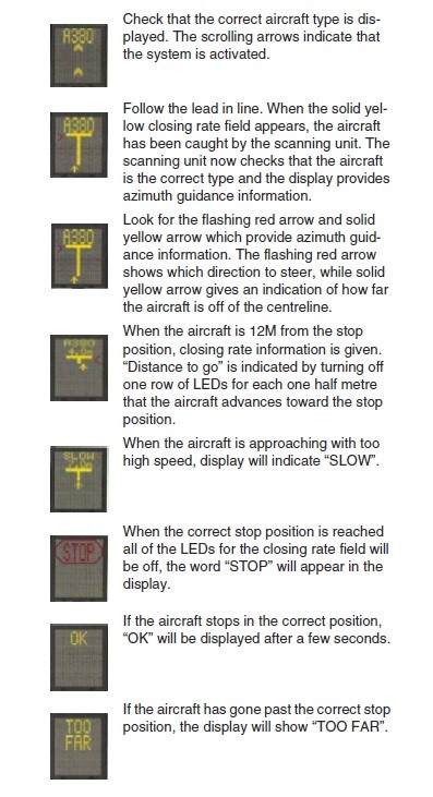
23.2.1 The VDGS has a built-in error detection program to inform the aircraft pilot of impending dangers during the docking procedures.
23.3 VDGS-Stands docking procedure in North Apron
Do not enter the stand if the display is blank or shows WAIT, STOP, FAILED, ERR or an incorrect aircraft, unless a marshaller is present. Contact GROUND for assistance.
OOSA AD 2.24 CHARTS RELATED TO AN AERODROME
| AERODROME CHART - ICAO | AERODROME CHART - ICAO |
| AIRCRAFT PARKING/DOCKING CHART - ICAO (NORTHERN APRONS) | AIRCRAFT PARKING/DOCKING CHART - ICAO (NORTHERN APRONS) |
| AIRCRAFT PARKING/DOCKING CHART - ICAO (SOUTH APRON) | AIRCRAFT PARKING/DOCKING CHART - ICAO (SOUTH APRON) |
| AERODROME OBSTACLE CHART - ICAO - TYPE A RWY 07/25 AD 2 | AERODROME OBSTACLE CHART - ICAO - TYPE A RWY 07/25 AD 2 |
| AERODROME OBSTACLE CHART - ICAO - TYPE B | AERODROME OBSTACLE CHART - ICAO - TYPE B |
| PRECISION APPROACH TERRAIN CHART - ICAO - RWY 07 | PRECISION APPROACH TERRAIN CHART - ICAO - RWY 07 |
| PRECISION APPROACH TERRAIN CHART - ICAO - RWY 25 | PRECISION APPROACH TERRAIN CHART - ICAO - RWY 25 |
| ATC SURVEILLANCE MINIMUM ALTITUDE CHART - ICAO | ATC SURVEILLANCE MINIMUM ALTITUDE CHART - ICAO |
| STANDARD DEPARTURE CHART INSTRUMENT - ICAO - RNAV (GNSS) RWY 07 | STANDARD DEPARTURE CHART INSTRUMENT - ICAO - RNAV (GNSS) RWY 07 |
| STANDARD DEPARTURE CHART INSTRUMENT - ICAO - RWY 07 | STANDARD DEPARTURE CHART INSTRUMENT - ICAO - RWY 07 |
| STANDARD DEPARTURE CHART INSTRUMENT - ICAO - RNAV (GNSS) RWY 25 | STANDARD DEPARTURE CHART INSTRUMENT - ICAO - RNAV (GNSS) RWY 25 |
| STANDARD DEPARTURE CHART INSTRUMENT - ICAO - RWY 25 | STANDARD DEPARTURE CHART INSTRUMENT - ICAO - RWY 25 |
| STANDARD ARRIVAL CHART INSTRUMENT - ICAO - RNAV (GNSS) RWY 07 | STANDARD ARRIVAL CHART INSTRUMENT - ICAO - RNAV (GNSS) RWY 07 |
| STANDARD ARRIVAL CHART INSTRUMENT - ICAO - RWY 07 | STANDARD ARRIVAL CHART INSTRUMENT - ICAO - RWY 07 |
| STANDARD ARRIVAL CHART INSTRUMENT - ICAO - RNAV (GNSS) RWY 25 | STANDARD ARRIVAL CHART INSTRUMENT - ICAO - RNAV (GNSS) RWY 25 |
| STANDARD ARRIVAL CHART INSTRUMENT - ICAO - RWY 25 | STANDARD ARRIVAL CHART INSTRUMENT - ICAO - RWY 25 |
| INSTRUMENT APPROACH CHART - ICAO - ILS RWY 07 | INSTRUMENT APPROACH CHART - ICAO - ILS RWY 07 |
| INSTRUMENT APPROACH CHART - ICAO - ILS RWY 25 | INSTRUMENT APPROACH CHART - ICAO - ILS RWY 25 |
| INSTRUMENT APPROACH CHART - ICAO - LOC RWY 07 | INSTRUMENT APPROACH CHART - ICAO - LOC RWY 07 |
| INSTRUMENT APPROACH CHART - ICAO - LOC RWY 25 | INSTRUMENT APPROACH CHART - ICAO - LOC RWY 25 |
| INSTRUMENT APPROACH CHART - ICAO - RNP RWY 07 | INSTRUMENT APPROACH CHART - ICAO - RNP RWY 07 |
| INSTRUMENT APPROACH CHART - ICAO - RNP RWY 25 | INSTRUMENT APPROACH CHART - ICAO - RNP RWY 25 |
| INSTRUMENT APPROACH CHART - ICAO - VOR RWY 07 | INSTRUMENT APPROACH CHART - ICAO - VOR RWY 07 |
| INSTRUMENT APPROACH CHART - ICAO - VOR RWY 25 | INSTRUMENT APPROACH CHART - ICAO - VOR RWY 25 |
| VISUAL APPROACH CHART - ICAO | VISUAL APPROACH CHART - ICAO |
OOSA AD 2.25 Visual segment surface (VSS) penetration
NIL